
MIL-STD-1553 Specification Tutorial
MIL-STD-1553B is the military specification defining a digital time division command/response multiplexed data bus. The 1553 data bus is a dual-redundant, bi-directional, Manchester II encoded data bus with a high bit error reliability. All bus communications are controlled and initiated by a main bus controller. Remote terminal devices attached to the bus respond to controller commands.
MIL-STD-1553B defines specifications for terminal device operation and coupling, word structure and format, messaging protocol and electrical characteristics.
> Download full detail MIL-STD-1553 Tutorial
MIL-STD-1553 Specification
MIL-STD-1553B was developed from the growing complexity of integrated avionics systems and the subsequent increase in the number of discrete interconnects between terminal devices. Direct point-to-point wiring became complex, expensive and bulky, requiring definition of a multiplex data bus standard. The first draft of a standard in 1968 by the aerospace branch of the Society of Automotive Engineers (SAE) laid the foundation for the US Air Force’s adoption of MIL-STD-1553 in 1973.
A tri-service version, MIL-STD-1553A was released in 1975 and utilized in the Air Force F-16 and the US Army AH-64A Apache Attack Helicopter. Notice 2, released in 1986 and superceding Notice 1 released in 1980, is a tri-service standard for RT design specs and defines how some bus options are to be used. Currently revised to MIL-STD-1553B, Notice 2, it has become the internationally accepted networking standard for integrating military platforms.
Military services and contractors originally adopted MIL-STD-1553 as an avionics data bus due to its highly reliable, serial, 1Mbit/s transfer rate and extremely low error rate of 1 word fault per 10 million words, on a dual-redundant architecture.
This reliability has proven equally effective on communication networks in submarines, tanks, target drones, missile and satellite systems, land-based and launch vehicles, and space system including the current International Space Station and Shuttle programs.
MIL-STD-1553B defines the data bus structure for interconnection of up to 31 remote terminal devices. A single controller device on the bus initiates the command/response communication with the remote devices. The remote and control devices are interconnected over 2 separate buses. Normal operation involves only the primary bus with the secondary bus available as redundant backup in the event of primary bus damage or failure.
MIL-STD-1553 Hardware Components
MIL-STD-1553 Bus Controller
The main function of the bus controller (BC) is to provide data flow control for all transmissions on the bus. In addition to initiating all data transfers, the BC must transmit, receive and coordinate the transfer of information on the data bus. All information is communicated in command/response mode – the BC sends a command to the RTs, which reply with a response.
The bus controller, according to MIL-STD-1553B, is the key part of the data bus system and the sole control of information transmission on the bus shall reside with the bus controller, which shall initiate all transmission. The bus can support multiple BCs, but only 1 can be active at a time.
Normal BC data flow control includes transmitting commands to RTs at predetermined time intervals. The commands may include data or requests for data (including status) from RTs. The BC has control to modify the flow of bus data based on changes in the operating environment. These changes could be a result of an air-to-ground attack mode changing to air-to-air, or the failure mode of a hydraulic system. The BC is responsible for detecting these changes and initiating action to counter them. Error detection may require the BC to attempt communications to the RT on the redundant, backup bus.
MIL-STD-1553 Remote Terminal
The remote terminal (RT) is a device designed to interface various subsystems with the 1553 data bus. The interface device may be embedded within the subsystem itself, or be an external interface to tie a non-1553 compatible device to the bus. As a function of the interface requirement, the RT receives and decodes commands from the BC, detects any errors and reacts to those errors. The RT must be able to properly handle both protocol errors (missing data, extra words, etc.) and electrical errors (waveform distortion, rise time violations, etc.). RTs are the largest segment of bus components.
MIL-STD-1553 Bus Monitor
The Bus Monitor (BM) listens to all messages on the bus and records selected activities. The BM is a passive device that collects data for real-time or post capture analysis. The BM can store all or portions of traffic on the bus, including electrical and protocol errors. BMs are primarily used for instrumentation and data bus testing.
MIL-STD-1553 Cabling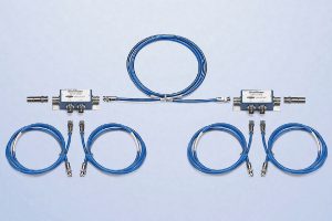
The MIL-STD-1553B definition of a data bus is “a twisted-shielded pair transmission line made up of a main bus and a number of attached stubs”. Shielding limits signal interference from outside sources and the twisted pair maintains message integrity through noise canceling.
MIL-STD-1553B specifies that all devices in the system will be connected to a redundant pair of buses, providing an alternate data path in the event of damage or failure of the primary bus path. Bus messages only travel on one of the buses at a time, determined by the bus controller.
Properly terminating the main data bus on each end makes the bus appear like an infinite line. Stub loading effects can be minimized on the bus by properly designed coupling.
MIL-STD-1553 Coupling
Coupling connects a terminal device to the main data bus via interconnecting buses called stubs. Connecting terminals creates a load on the main bus, creating impedance mismatches and resultant signal reflections that can distort and degrade signal quality on the bus. System error rate performance and good signal to noise ratio require a balance between stub impedance being low enough to provide adequate terminal signal levels but high enough to reduce signal distortion from reflections. MIL-STD-1553B allows two methods of coupling terminal devices to the main bus: Direct and Transformer coupling.
MIL-STD-1553 Direct Coupling
Direct coupled connections are wired directly to the bus cabling. The isolation resistors and transformer are internal to the terminal device, not requiring additional coupling hardware. Direct coupled connections can only be used with stub lengths of less than one foot.
Isolation resistors provide some protection for the main bus in the event of a stub or terminal short, but MIL-STD-1553B cautions the use of direct coupling because a terminal short could disable the entire bus. Direct stubs can also cause significant impedance mismatches on the bus.
MIL-STD-1553 Transformer Coupling
Transformer coupling utilizes a second isolation transformer, located external to the terminal device, in its own housing with the isolation resistors. Transformer coupling extends the stub length to 20 feet and provides electrical isolation, better impedance matching and higher noise rejection characteristics than direct coupling. The electrical isolation prevents a terminal fault or stub impedance mismatch from affecting bus performance.
MIL-STD-1553 Bus Topology
Bus topology refers to the physical layout and connections of each device attached to the data bus. Single level topologies are the most basic, easy to design and widely implemented layouts with all terminal devices connected to a single bus.
Multiple level topologies are designed by interconnecting single level buses so data from one bus can be transferred on another bus. Buses interconnected in a multiple level topology can have equal control over data flow, which helps retain autonomy for each bus with the greatest isolation between them. A hierarchical format between multiple level buses establishes local (subordinate) buses and global (superior) buses with the global bus having control over local, subordinate buses.
MIL-STD-1760C
MIL-STD-1760C, released April 15, 1991 defines implementation requirements for the Aircraft/Store Electrical Interconnection System (AEIS) between aircraft and stores. A store is any external device attached to the aircraft and includes permanent devices – ECM, LANTIRN, fuel tanks – and devices designed to separate – bombs, missiles, etc.
MIL-STD-1760C states “the data bus interface shall comply with the requirements of MIL-STD-1553” with some additional requirements. In this case, the 1553 bus is the controlling bus over the subordinate 1760 AEIS bus. That 1760 bus may then control a 1553 bus system within a store to communicate directly with weapons, navigational aids or communications subsystems.
The Aircraft Station Interface (ASI) is the connection to the aircraft. Umbilical cabling connects the ASI to the store connector, the Mission Store Interface (MSI). The ASI can also connect – through an umbilical cable – to a Carriage Store Interface (CSI) to tie in multiple mission stores. Carriage Store Station Interfaces (CSSI) then connects to MSIs via umbilical cables.
Mission stores contain embedded 1553 RTs that must be capable of BC-RT, RT-BC and RT-RT message transfers with the aircraft functioning as the bus controller. Dynamic bus control is not allowed on a MIL-STD-1760C bus design.
MIL-STD-1553 Test Procedures
Testing MIL-STD-1553B components validate the functional capability of the bus design. Testing the design of a bus requires testing message formats, mode commands, status word bits and coupling techniques as they apply to each remote terminal, bus controller and monitor device. Five levels of testing have been developed to verify MIL-STD-1553B bus design compliance:
Developmental Testing – Implemented at the circuit level to determine operational capability of the circuit design. Standard test techniques also validate operating characteristics over the required environmental operating range – i.e. temperature, humidity, vibration, etc.
Design Verification – Carried out on pre-production prototypes to insure 1553 compliance, as well as systems specifications on the design unit itself. This testing level verifies hardware/software requirements before production begins.
Production Testing – Performed on production equipment as a final Quality Assurance check or during the production process on subassembly items. Often applying a subset of the design verification tests, > Production Testing verifies circuit operation and proper sequence operations such as error message validation and mode code operation.
Systems Integration Testing – Applied while integrating bus components into a system and insures interoperability of the joined components. During Systems Integration Testing, network hardware and software are combined and assessed to insure proper data flow control.
Field/Operational Testing – Implemented as a final design test of the system under actual operating conditions. Known as Developmental Test/Operational Test – DT/OT – this level of testing verifies operational integrity of the components/system in installed, fully functional bus networks.